
AWS Site-to-Site VPN (IPSec) with IPv6
Notice: This article is more than 5 years old. It might be outdated.
Recently AWS released support for IPv6 traffic over the AWS Site-to-Site VPN (IPSec). The setup of the AWS Site-to-Site VPN has always been quite straight forward and thanks to the downloadable configuration files at times even trivial. With the introduction of IPv6 support this is unfortunately no longer the case. Therefore this blog post will guide you around some of the pitfalls of setting up an AWS Site-to-Site VPN with IPv6 support, hoping that they will eventually be removed and this post become unnecessary.
Constraints
A few constraints apply when using AWS Site-to-Site VPN (IPSec) with IPv6:
- The outside tunnel IP addresses - which are the public non-RFC1918 addresses - still only support IPv4. You can only use IPv6 on the inside of the tunnel, in order to carry IPv6 traffic between your on-premises network and AWS.
- You have to use an AWS Transit Gateway (TGW) as the AWS termination of your VPN. Site-to-Site VPNs to a Virtual Private Gateways (VGW) do not support IPv6.
- You cannot retrofit existing Site-to-Site connections with IPv6, but need to create a new connection.
- A Site-to-Site VPN connection can only support IPv4, or IPv6. This means that if you need to carry both IPv4 and IPv6 traffic between AWS and on-premises you need to create two separate connections, one for IPv4 and one for IPv6 (See Figure 1).
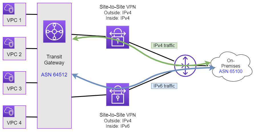
As each AWS Site-to-Site VPN connection consist of two tunnels, in the case of supporting IPv4/IPv6 Dualstack traffic you will therefore end up with a total of four tunnels, two for IPv4 traffic and two for IPv6 traffic. Also note that this means you’ll be paying separately for the tunnel carrying the IPv4 traffic as well as for the tunnel carrying the IPv6 traffic.
Configuration
AWS Setup
The creation of a Site-to-Site VPN connection is straight forward and only differs from its IPv4 counterpart by setting the “Tunnel Inside IP version” to IPv6 instead of IPv4 (See Figure 2).
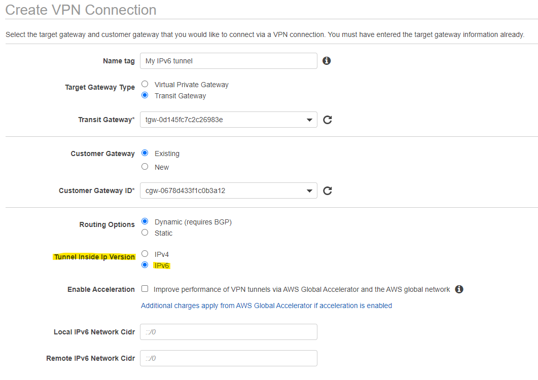
The IPv6 enabled Site-to-Site VPN connection also supports defining the IPv6 addresses used within the tunnel yourself. If you want to make use of this capability you have to select a /126 IPv6 subent out of the fd00::/8 Unique local address address range. This is useful to prevent IP address collisions across multiple tunnels. Although with IPv6 addresses, such a collision is much less likely than with IPv4.
Customer-side Configuration
Basic configuration information
When configuring the costumer-side of the solution, the challenges will start. Having a look at the Tunnel details for a newly created AWS Site-to-Site VPN with IPv6 support will yield some surprising results (See Figure 3).
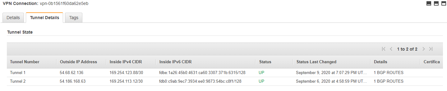
You’ll see that for both tunnels “Inside IPv4 CIDRs” from the 169.254.0.0/16 Link-local address range will be shown. As mentioned previously an AWS Site-to-Site connection - and thereby its tunnels - only supports either IPv4 or IPv6. As this is an IPv6 enabled tunnel, the displayed Inner IPv4 CIDRs are irrelevant from a tunnel transport perspective. You can completely ignore them when configuring the tunnel itself. The provided information does come in handy with regards to the BGP router ID. In the above case, with Tunnel 1 the AWS side of the BGP session uses the BGP router ID of 169.254.123.89. To prevent collisions you should therefore not use the same BGP router ID on your side.
Next you will notice that for the “Inside IPv6 CIDRs” the addresses are provided with a /128 netmask - which is the IPv6 equivalent of /32 and therefore a “host-only” netmask. This netmask therefore only contains a single IP address. Yet the documentation clearly calls out that these “Inside IPv6 CIDRs” should be a /126 IPv6 CIDR block, which includes 4 IPv6 addresses. A /126 IPv6 CIDR is the equivalent of a /30 IPv4 CIDR. Also the provided IPv6 address from the fd00::/8 Unique local address address range ends in an odd number and is therefore not a network address, which always end in even numbers. Turns out that the displayed IPv6 address is actually the AWS side of the inner connection.
So with the value of “fdbe:1a26:45b0:4631:ca60:3307:371b:6315/128” displayed in the provided example, the relevant IPv6 information would be:
- Subnet (aka CIDR): fdbe:1a26:45b0:4631:ca60:3307:371b:6314/126
- AWS-side interface address: fdbe:1a26:45b0:4631:ca60:3307:371b:6315/126
- Customer-side address: fdbe:1a26:45b0:4631:ca60:3307:371b:6316/126
You should notice the pattern for constructing the necessary IPv6 information:
- Subnet (aka CIDR): Provided IPv6 address - 1
- AWS-side interface address: Provided IPv6 address
- Customer-side address: Provided IPv6 address + 1
Just keep in mind that IPv6 addresses use hex digits, which start with 0,1,2,.. then continue with ..,8,9,A,B,.. and end with ..,E,F.
You can double check your conversion math knowing that the used netmask is a /128, allowing IPv6 subnets with 4 addresses. Therefore 4 different combinations of trailing IPv6 digits exist:
- Subnet (aka CIDR): Must always end in 0,4,8,C
- AWS-side interface address: Must always end in 1,5,9,D
- Customer-side address: Must always end in 2,6,A,E
Notice: In the meantime the representation of the Inside IPv6 CIDR in the AWS Console has been fixed. You should notice that now the Subnet (AKA CIDR) is displayed with the correcet subnet mask of /126. Therefore in the above example the AWS Console would now display fdbe:1a26:45b0:4631:ca60:3307:371b:6314/126.
Configuration download
The next challenge you will notice is that when downloading the downloadable configuration files from the AWS Console, it does not include any IPv6 address information. Instead for the inner address it includes IPv4 address information that are irrelevant as already pointed out.
Nevertheless you can leverage the downloadable configuration file for the Internet Key Exchange (IKE) and IPSec Configuration of your tunnels. These two sections within the file can be used without any changes, unless you diverted with your IKE or IPSec settings from the default values. Because these downloadable configuration files are only baseline examples that assume default values.
Tunnel Interface Configuration
With that the Tunnel Interface Configuration has to be adapted from IPv4 to IPv6. Using a Cisco IOS configuration as an example, the downloadable configuration file will provide the following Interface Configuration.
interface Tunnel1
  ip address 169.254.123.90 255.255.255.252
  ip virtual-reassembly
  tunnel source 198.51.100.123
  tunnel destination 54.68.62.136
  tunnel mode ipsec ipv4
  tunnel protection ipsec profile ipsec-vpn-0b1561f60da62e5eb-0
  ip tcp adjust-mss 1379
Within this configuration we have to replace the inner IPv4 address with an IPv6 address and also specify that IPv6 should be used within the inside of the tunnel. The outer IP address remains to be an IPv4 address. The resulting corrected configuration using the IPv6 address as outlined in the previous section becomes as follows.
interface Tunnel1
 no ip address
 ip virtual-reassembly
 ipv6 address FDBE:1A26:45B0:4631:CA60:3307:371B:6316/126
 tunnel source 198.51.100.123
 tunnel destination 54.68.62.136
 tunnel mode ipsec ipv4 v6-overlay
 tunnel protection ipsec profile ipsec-vpn-0b1561f60da62e5eb-0
 ip tcp adjust-mss 1379
Border Gateway Protocol (BGP) Configuration
Next the Border Gateway Protocol (BGP) Configuration also needs to be adapted, replacing the IPv4 configuration with a corresponding IPv6 configuration.
The downloadable configuration will provide the following BGP configuration.
router bgp 65000
  neighbor 169.254.123.89 remote-as 64512
  neighbor 169.254.123.89 activate
  neighbor 169.254.123.89 timers 10 30 30
  address-family ipv4 unicast
    neighbor 169.254.123.89 remote-as 64512
    neighbor 169.254.123.89 timers 10 30 30
    neighbor 169.254.123.89 activate
    neighbor 169.254.123.89 soft-reconfiguration inbound
As we want to run BGP over the inner IPv6 connection, we again have to replace all IPv4 configuration items with the corresponding IPv6 addresses. The result will look as follows.
router bgp 65000
  neighbor FDB0:C9AB:9EC7:3934:EE0:9873:54BC:C8F1 remote-as 64512
  neighbor FDB0:C9AB:9EC7:3934:EE0:9873:54BC:C8F1 activate
  neighbor FDB0:C9AB:9EC7:3934:EE0:9873:54BC:C8F1 timers 10 30 30
  address-family ipv6 unicast
    neighbor FDB0:C9AB:9EC7:3934:EE0:9873:54BC:C8F1 remote-as 64512
    neighbor FDB0:C9AB:9EC7:3934:EE0:9873:54BC:C8F1 timers 10 30 30
    neighbor FDB0:C9AB:9EC7:3934:EE0:9873:54BC:C8F1 activate
    neighbor FDB0:C9AB:9EC7:3934:EE0:9873:54BC:C8F1 soft-reconfiguration inbound
Here you effectively have to replace the unusable IPv4 address for the neighbor with the correct IPv6 address of that neighbor and change the address-family section from IPv4 to IPv6.
Validation
As a final step, we can validate that IPv6 routes are being learned from the TGW via the Site-to-Site VPN.
CSR1000V-01#sh ipv6 route bgp
IPv6 Routing Table - default - 13 entries
Codes: C - Connected, L - Local, S - Static, U - Per-user Static route
       B - BGP, R - RIP, H - NHRP, I1 - ISIS L1
       I2 - ISIS L2, IA - ISIS interarea, IS - ISIS summary, D - EIGRP
       EX - EIGRP external, ND - ND Default, NDp - ND Prefix, DCE - Destination
       NDr - Redirect, RL - RPL, O - OSPF Intra, OI - OSPF Inter
       OE1 - OSPF ext 1, OE2 - OSPF ext 2, ON1 - OSPF NSSA ext 1
       ON2 - OSPF NSSA ext 2, la - LISP alt, lr - LISP site-registrations
       ld - LISP dyn-eid, lA - LISP away, le - LISP extranet-policy
       lp - LISP publications, a - Application, m - OMP
B   2600:1234::/64 [20/100]
     via FDBE:1A26:45B0:4631:CA60:3307:371B:6315
     via FDB0:C9AB:9EC7:3934:EE0:9873:54BC:C8F1
B   2600:1A14:5DE:DB00::/56 [20/100]
     via FDBE:1A26:45B0:4631:CA60:3307:371B:6315
     via FDB0:C9AB:9EC7:3934:EE0:9873:54BC:C8F1
B   2600:1A16:807:3A00::/56 [20/100]
     via FDBE:1A26:45B0:4631:CA60:3307:371B:6315
     via FDB0:C9AB:9EC7:3934:EE0:9873:54BC:C8F1
In this case we can see that a total of three prefixes is learned, whereas the first prefix is originated on the TGW via a summary route, while the other two prefixes correspond to VPCs.
Summary
This blog post guided you around some of the pitfalls when setting up an IPv6 capable AWS Site-to-Site VPN connection. It covered some of the rather cosmetic imperfections within the AWS Console around unusable IPv4 addresses, as well as generating a working Customer Gateway (CGW) configuration based on the downloadable configuration files.
Leave a comment