
BGP route summarization with AWS Transit Gateway
Notice: This article is more than 6 years old. It might be outdated.
This blog post will look at using BGP Route Aggregation from the AWS Transit Gateway via IPSec VPN to a customer gateway. While the example configuration and output provided for the customer gateway are using a Cisco CSR1000V with IOS-XE, you can replicate the same with e.g. Ubuntu Linux, StrongSwan and FFRouting. Have a look at the previous post “AWS Site-to-Site VPN with IPSec VPN (Strongwan) and BGP (FRRouting)”, which describes how to setup such a testbed.
BGP Route Aggregation
BGP Route Aggregation (RA) - also sometimes referred to as BGP Route Summarization - is a method to minimize the size of the routing table. RA reduces the size of the global routing table, decreases routers’ workload and saves network bandwidth. As an example: Instead of announcing the four routes of 192.168.0.0/24, 192.168.1.0/24, 192.168.2.0/24, and 192.168.3.0/24, one can announce the single route of 192.168.0.0/22 instead.
AWS Transit Gateway
AWS Transit Gateway is a service that enables customers to connect their Amazon Virtual Private Clouds (VPCs) and their on-premises networks to a single gateway. For on-premises connectivity the AWS Transit Gateway allows you to leverage AWS Site-to-Site VPNs (IPSec) or AWS Direct Connect via AWS Direct Connect Gateways (See Figure 2).
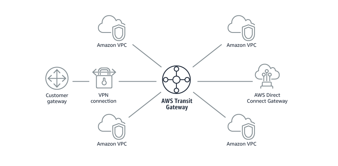
A transit gateway acts as a regional virtual router for traffic flowing between your virtual private clouds (VPC) and VPN or DX connections. A transit gateway scales elastically based on the volume of network traffic. Routing through a transit gateway operates at layer 3, where the packets are sent to a specific next-hop attachment, based on their destination IP addresses.
The AWS Transit Gateway’s hub and spoke model simplifies management and reduces operational costs because each network only has to connect to the Transit Gateway and not to every other network. Any new VPC is simply connected to the Transit Gateway and is then automatically available to every other network that is connected to the Transit Gateway. This ease of connectivity makes it easy to scale your network as you grow.
BGP Route Aggregation
Problem Description
As previously mentioned, AWS Transit Gateway allows you to connect multiple AWS VPCs to on-premises networks via an IPSec VPN or Direct Connect. In the case of an AWS IPSec VPN connection, AWS Transit Gateway will announce over BGP a separate route for each of these connected VPCs.
Figure 2 shows an example, where the four subnets 172.16.1.0/24, 172.16.2.0/24, 172.16.3.0/24, and 172.16.4.0/24 correspond to a separate VPC each.
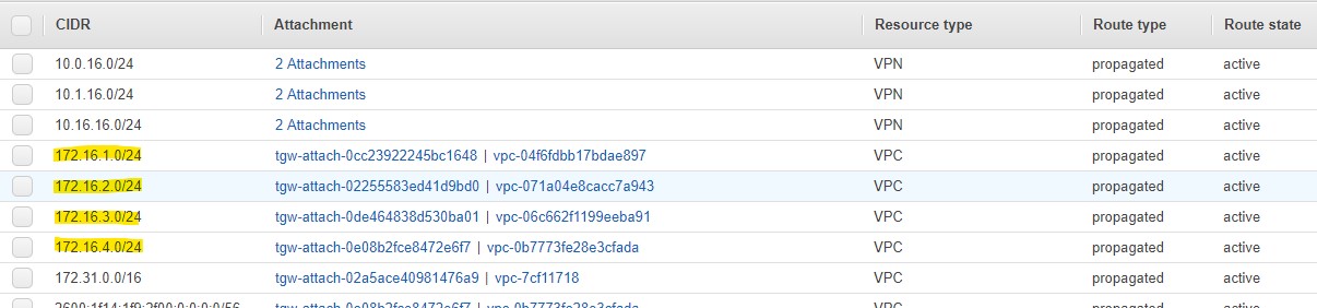
On the customer gateway the routes for these four VPCs are then received separately as individual routes.
CSR100V-01#sh ip route bgp
Codes: L - local, C - connected, S - static, R - RIP, M - mobile, B - BGP
       D - EIGRP, EX - EIGRP external, O - OSPF, IA - OSPF inter area
       N1 - OSPF NSSA external type 1, N2 - OSPF NSSA external type 2
       E1 - OSPF external type 1, E2 - OSPF external type 2
       i - IS-IS, su - IS-IS summary, L1 - IS-IS level-1, L2 - IS-IS level-2
       ia - IS-IS inter area, * - candidate default, U - per-user static route
       o - ODR, P - periodic downloaded static route, H - NHRP, l - LISP
       a - application route
       + - replicated route, % - next hop override, p - overrides from PfR

Gateway of last resort is 10.0.1.1 to network 0.0.0.0

      10.0.0.0/8 is variably subnetted, 6 subnets, 2 masks
B        10.1.16.0/24 [20/100] via 169.254.15.221, 1d01h
                      [20/100] via 169.254.13.253, 1d01h
B        10.16.16.0/24 [20/100] via 169.254.15.221, 1d01h
                       [20/100] via 169.254.13.253, 1d01h
      172.16.0.0/24 is subnetted, 4 subnets
B        172.16.1.0 [20/100] via 169.254.15.221, 1d01h
                    [20/100] via 169.254.13.253, 1d01h
B        172.16.2.0 [20/100] via 169.254.15.221, 1d01h
                    [20/100] via 169.254.13.253, 1d01h
B        172.16.3.0 [20/100] via 169.254.15.221, 1d01h
                    [20/100] via 169.254.13.253, 1d01h
B        172.16.4.0 [20/100] via 169.254.15.221, 1d01h
                    [20/100] via 169.254.13.253, 1d01h
B     172.31.0.0/16 [20/100] via 169.254.15.221, 1d01h
                    [20/100] via 169.254.13.253, 1d01h
CSR100V-01#
As in this example the four subnets for the VPCs, as well as the subnet for the default VPC of 172.31.0.0/16 are part of the aggregate route of 172.16.0.0/12 it might make more sense to announce this single aggregate over the IPSec VPN instead of the individual more specific routes (See Figure 3).
Especially as you add further VPCs with a netblock from the 172.16.0.0/12 block, this summarization will keep the routing table on the customer gateway smaller.
Static TGW Route
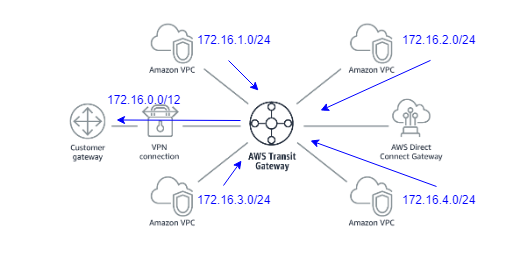
A common mechanism to crate a BGP route aggregation with physical routers is to create a static discard route on the source router. This means that for an aggregate address - in our case this is 172.16.0.0/12 - a static route pointing to a null interface is created. As a result this aggregate route will be propagated via BGP. Once packets reach this router, the more specific routes will determine how to further route the packet.
While The AWS Transit Gateway supports blackhole routes, these routes are not propagated via BGP over the IPSec tunnels. Instead you have to create a regular static route and point it at a random VPC (See Figure 4).
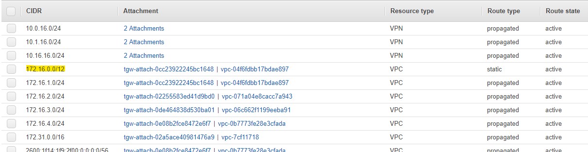
As a result the customer gateway will now receive the aggregate route of 172.16.0.0/12 besides the 5 more specific routes for 172.16.1.0/24, 172.16.2.0/24, 172.16.3.0/24, 172.16.4.0/24, and 172.31.0.0/16.
CSR100V-01#sh ip route bgp
Codes: L - local, C - connected, S - static, R - RIP, M - mobile, B - BGP
       D - EIGRP, EX - EIGRP external, O - OSPF, IA - OSPF inter area
       N1 - OSPF NSSA external type 1, N2 - OSPF NSSA external type 2
       E1 - OSPF external type 1, E2 - OSPF external type 2
       i - IS-IS, su - IS-IS summary, L1 - IS-IS level-1, L2 - IS-IS level-2
       ia - IS-IS inter area, * - candidate default, U - per-user static route
       o - ODR, P - periodic downloaded static route, H - NHRP, l - LISP
       a - application route
       + - replicated route, % - next hop override, p - overrides from PfR

Gateway of last resort is 10.0.1.1 to network 0.0.0.0

      10.0.0.0/8 is variably subnetted, 6 subnets, 2 masks
B        10.1.16.0/24 [20/100] via 169.254.15.221, 1d01h
                      [20/100] via 169.254.13.253, 1d01h
B        10.16.16.0/24 [20/100] via 169.254.15.221, 1d01h
                       [20/100] via 169.254.13.253, 1d01h
B     172.16.0.0/12 [20/100] via 169.254.15.221, 00:00:43
                    [20/100] via 169.254.13.253, 00:00:43
      172.16.0.0/24 is subnetted, 4 subnets
B        172.16.1.0 [20/100] via 169.254.15.221, 1d01h
                    [20/100] via 169.254.13.253, 1d01h
B        172.16.2.0 [20/100] via 169.254.15.221, 1d01h
                    [20/100] via 169.254.13.253, 1d01h
B        172.16.3.0 [20/100] via 169.254.15.221, 1d01h
                    [20/100] via 169.254.13.253, 1d01h
B        172.16.4.0 [20/100] via 169.254.15.221, 1d01h
                    [20/100] via 169.254.13.253, 1d01h
B     172.31.0.0/16 [20/100] via 169.254.15.221, 1d01h
                    [20/100] via 169.254.13.253, 1d01h
CSR100V-01#
Customer gateway route filtering
While this is already a good step in the right direction, still receiving the individual more specific routes on the customer defeats the purpose of route aggregation. While Cisco IOS e.g. has the command aggregate-address address / length summary-only for solely announcing the summary route, the AWS Transit Gateway is missing a similar capability.
Here instead we have to filter undesired prefixes as part of the BGP session in the customer gateway. This way we can accept only the aggregate prefixes, preventing and more specific route to be installed into the customer gateway route table.
To do so, we first create an ip prefix list with the desired prefixes that we want to receive. Next we create a route map matching this prefix list. Last but not least the route map is applied on incoming BGP connections for each configured BGP peer, aka neighbors.
router bgp 65000
 bgp log-neighbor-changes
 neighbor 169.254.13.253 remote-as 64512
 neighbor 169.254.13.253 timers 10 30 30
 neighbor 169.254.15.221 remote-as 64512
 neighbor 169.254.15.221 timers 10 30 30
 !
 address-family ipv4
  network 10.0.16.0 mask 255.255.255.0
  neighbor 169.254.13.253 activate
  neighbor 169.254.13.253 soft-reconfiguration inbound
  neighbor 169.254.13.253 route-map REJECT in
  neighbor 169.254.15.221 activate
  neighbor 169.254.15.221 soft-reconfiguration inbound
  neighbor 169.254.15.221 route-map REJECT in
  maximum-paths eibgp 2
 exit-address-family
!

ip prefix-list incoming seq 5 permit 10.1.16.0/24
ip prefix-list incoming seq 10 permit 10.16.16.0/24
ip prefix-list incoming seq 15 permit 172.16.0.0/12
!
route-map REJECT permit 10
 match ip address prefix-list incoming
!
As a result our customer gateway will now only receive the aggregate prefix, but none of the more specific routes.
CSR100V-01#sh ip route bgp
Codes: L - local, C - connected, S - static, R - RIP, M - mobile, B - BGP
       D - EIGRP, EX - EIGRP external, O - OSPF, IA - OSPF inter area
       N1 - OSPF NSSA external type 1, N2 - OSPF NSSA external type 2
       E1 - OSPF external type 1, E2 - OSPF external type 2
       i - IS-IS, su - IS-IS summary, L1 - IS-IS level-1, L2 - IS-IS level-2
       ia - IS-IS inter area, * - candidate default, U - per-user static route
       o - ODR, P - periodic downloaded static route, H - NHRP, l - LISP
       a - application route
       + - replicated route, % - next hop override, p - overrides from PfR

Gateway of last resort is 10.0.1.1 to network 0.0.0.0

      10.0.0.0/8 is variably subnetted, 6 subnets, 2 masks
B        10.1.16.0/24 [20/100] via 169.254.15.221, 1d01h
                      [20/100] via 169.254.13.253, 1d01h
B        10.16.16.0/24 [20/100] via 169.254.15.221, 00:00:40
                       [20/100] via 169.254.13.253, 00:00:40
B     172.16.0.0/12 [20/100] via 169.254.15.221, 00:27:23
                    [20/100] via 169.254.13.253, 00:27:23
CSR100V-01#
Summary
This blog post walked you through configuring BGP route summarization with AWS Transit Gateway for attachments over IPSec VPN. Keep in mind, that with the AWS Transit Gateway and a Direct Connect Gateway attachment, this approach is not applicable as you are effectively specifying the IP prefixes to be announced over Direct Connect manually via allowed prefixes.
Leave a comment