
SDDC Architecture – Basic Design Elements
Notice: This article is more than 10 years old. It might be outdated.
This article is part of a series of articles, focusing on the architecture of an SDDC as well as some of its design elements.
Requirements
A Software Defined Data Center promises to be the new underpinning or platform for delivering today’s and tomorrow’s IT services. As such this next generation infrastructure needs to address some shortcomings of today’s infrastructure in order to be successful:
- Highly automated operation at Scale: Leaner organization that scales sub-linearly with an operating model build around automation. Leverage modular web-scale designs for unhampered scalability.
- Hardware and Software efficiencies: Support on-demand scaling for varying capacity needs. Improved resource pooling to drive increased utilization of resources and reduce cost.
- New and old business needs: Support legacy applications with traditional business continuity and disaster recovery, besides new cloud-native applications.
Introduction
The SDDC architecture is based on five basic design elements, which we will cover in this post in more detail (See Figure 1).
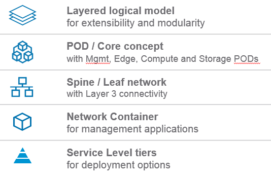
These design elements allow us achieve the previously stated design goals for an SDDC and are crucial to its success. They allow us to create a simple, yet powerful design.
Layered logical model
Basing the SDDC on a layered logical model enables a very high level of modularity (See Figure 2).
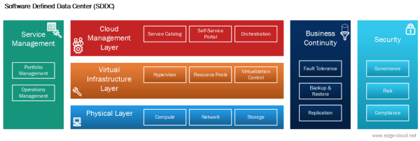
With this approach it is possible to replace the Cloud Management System (CMS) or even to run multiple CMS at the same time, on top of the same Virtual Infrastructure.
This means that VMware Integrated OpenStack (VIO) could easily replace VMware vRealize Automation as the CMS. As this change solely happens in the Cloud Management Layer, no changes are necessary to the underlying Virtual Infrastructure Layer or any other layer.
Or in another scenario it would be possible to run both VMware vCloud Director (vCD) and VMware Integrated OpenStack in parallel within the Cloud Management Layer on top of the same Virtual Infrastructure Layer.
It’s important to point out that in this case workloads would be exclusively managed by one of the two CMS.
POD / Core concept
The POD and core concept leverages individually designed point-of-delivery (POD), which connect to a common routed core layer. The routed core spans multiple PODs of different type and generation, treating them as an atomic building block and providing fast and simple interconnect.
This approach of scaling out in concrete chunks matches the incremental demand of modern data centers: PODs are designed, engineered, installed and retired as a distinct unit. As such an SDDC can comprise multiple generations of a pod, sitting next to each other, attached to the same shared core and allow an iterative approach, where each pod generation improves on the previous one.
Further splitting PODs by functional capability into Storage POD, Management POD, Compute POD and Network Edge POD, you also gain the ability to easily scale your SDDC capacity and capability based on demand, leading to even higher flexibility (See Figure 3).
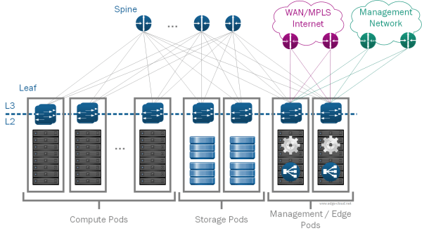
L3 Spine / Leaf network
For many years the predominant data center network design was the three-tier approach of a Core (Layer 3), Aggregation (Layer 2 / Layer 3), Access (Layer 2) tiers. This design approach has been very successful over the last 20 years, allowing network architects to design highly reliable and scalable networks, recent industry developments are breaking the underlying assumptions:
The three-tier network assumes a significant price difference between network device capable of Layer 3 routing vs. Layer 2 Switching, which is no longer the case. It further assumes that traffic is primarily exchanged between servers and the outside world (north-south traffic), while today server-to-server traffic (east-west traffic) is more common. Last but least it assumes that the interface speed at the Core and Aggregation tier is significantly higher than in the access layer, which also isn’t true anymore thanks to the prevalence of 10 Gigabit Ethernet equipped servers.
At the same time the traditional three-tier design fails to address innovation in modern data centers through its lack of modularity and rigidness. This hampers fast iterations and experimentation, while also preventing to keep up with price/performance improvements in the industry.
Consequently the time has come for a new approach to data center network design, based on hyper- or webscale data center center design. Despite their massive scale, hyper- or webscale data centers leverage a network design that starts small and innovates quickly. As such the key differentiator is that a Spine / Leaf network supports you to grow organically in incremental blocks of capacity, starting small each time, while at the same time allowing you to scale almost beyond imagination. Such an approach works very well hand-in-hand with the above mentioned POD / Core concept.
Management Applications Network Container
With the network containers for management applications we place each management application in a dedicated network container with an NSX Edge acting as firewall, load balancer, and gateway of that container. With the previously presented management applications this means that we have one container for VMware vRealize Automation, another one for vRealize Operations and a third one for vRealize LogInsight.
These network container then connect to a “business network” on which end-user facing services - such as the vRealize Automation Web interface - are presented, as well as a “management network” via which infrastructure admins connect. Nevertheless components within each network container are protected against these two networks, which present two different trust zones, besides the network container as a third trust zone.
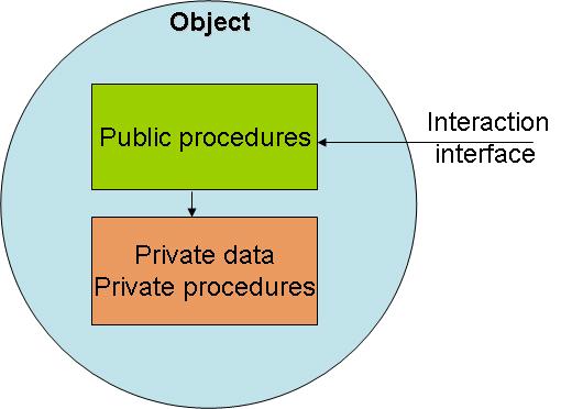
To draw an analogy of what this means: Let’s look at the Object Oriented (OO) design approach, well known from software engineering (See Figure 4).
With the SDDC network container, we want to enforce access to services through the front door, via the Load Balancer. In OO this is equivalent to accessing an object via methods.
With the network container we want to prevent access through the “backdoor” or direct node access for end-users. In OO this is equivalent to accessing attributes directly, which would violate the OO concept.
As a result network container provide us with a few benefits:
- Security: Granular yet simple control who can access what kind of service through the “front door” (load balancer).
- Modularity: Replace or upgrade an application without breaking the entire SDDC as dependencies are established via well-know interfaces.
-
Simplicity: Reduce the number of required IP addresses on the business network, keeping the integration effort low and enabling deployment on the Internet.
In other words: Keep it simple. No dynamic routing towards the corporate network is necessary. As a result we have less components and less configuration.
- BC/DR: Simplifies the Business Continuity/Disaster Recovery story with VMware Site Recovery Manager.
Service Level tiers
Especially with the ambition to address new and old business needs via the support of legacy applications with traditional business continuity and disaster recovery needs, in addition to new cloud-native applications, a one-size fits all approach doesn’t work anymore. Such an approach would either become prohibitively expensive by providing all workloads with the same level of high end treatment or would fall short on the provided business value through capabilities.
Yet at the same time you also want to limit customization in order to be able to maintain self-service capabilities, as each customization adds complexity and cost.
The solution here is to use a small set of distinct service level tiers. Each service tier implements a certain capability along the spectrum of capabilities. As such it would e.g. be possible to workloads different data stores with varying IOPS.
Another example would be the ability to offer three levels of backup capabilities: The lowest tier, usually called bronze, would offer no backup whatsoever. The next tier, usually called silver, would offer backups within the same region. The most advanced tier, usually called gold, would offer backups within and across regions.
Summary
The ultimate goal of the SDDC is to provide business value through a simple, stable and understandable architecture.
The above presented basic design elements of the SDDC not only allow us to clearly communicate the elements and their benefits of the SDDC, but are crucial for leveraging these benefits in a real-life SDDC installation.
Leave a comment