
SDDC Architecture - Business Continuity with multiple regions
Notice: This article is more than 8 years old. It might be outdated.
This article is part of a series of articles, focusing on the architecture of an SDDC via VMware Validated Designs.
Requirements
A Software Defined Data Center promises to be the new underpinning or platform for delivering today’s and tomorrow’s IT services. As such this next generation infrastructure needs to address some shortcomings of today’s infrastructure in order to be successful:
- Highly automated operation at Scale: Leaner organization that scales sub-linearly with an operating model build around automation. Leverage modular web-scale designs for unhampered scalability.
- Hardware and Software efficiencies: Support on-demand scaling for varying capacity needs. Improved resource pooling to drive increased utilization of resources and reduce cost.
- New and old business needs: Support legacy applications with traditional business continuity and disaster recovery, besides new cloud-native applications.
Conceptual Design
This solution assumes that two regions exist. Under normal circumstances each region consists of an Software Defined Data Center (SDDC) installation, where components of the virtual infrastructure layer exist independently in both regions for the Management and Compute stack.
The management applications VMware vRealize Automation together with VMware vRealize Orchestrator and VMware vRealize Operations only exist in the primary region, while they manage and monitor resources in both regions. In a case of a failure these applications will be failed over to the secondary location, using VMware Site Recovery Manager (SRM).
For all other management applications a dedicated instance needs to exist per region. This includes vRealize Log Insight, of which a dedicated instance exists in both regions (See Figure 1).
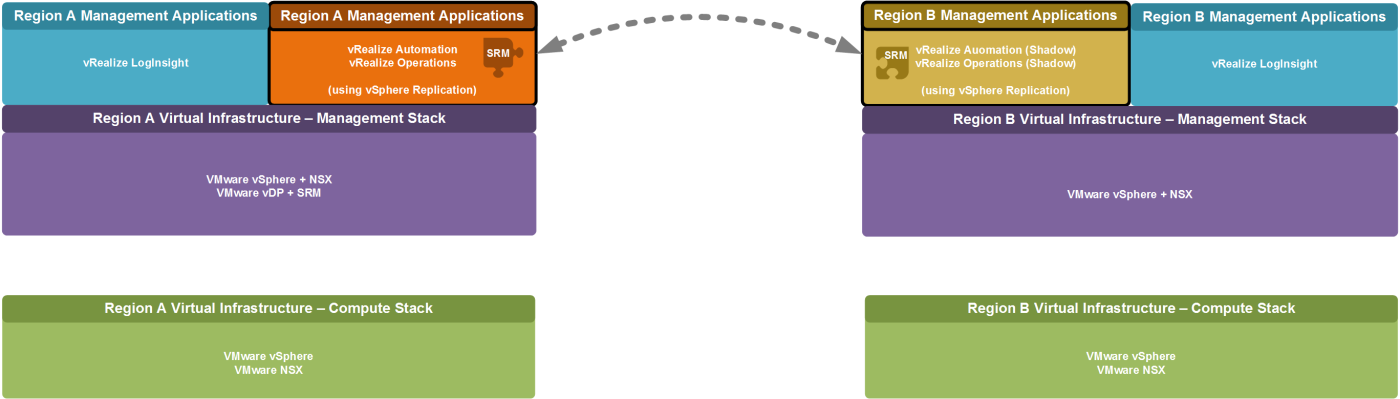
This underlying design limits the management components that need to be moved between the failed primary region and the secondary region in case of a failure of the primary region. At the same time it ensures that under normal circumstance both regions can provide sufficient services in an active/active manner. The design also ensure that the excess capacity that needs to be available for accepting a failed-over workload is kept to a minimum.
After a failure of either region, the overall SDDC management capabilities are still available. Solely the workload capacity has been reduced by whatever percentage of capacity the failed region makes up of the total capacity.
We will look at BC/DR capabilities for the workloads of the SDDC separately.
Disaster Recovery Design Example
Within this example, the SDDC includes two locations: A protected “Region A” in San Francisco, CA and a “Region B” for recovery purposes in Los Angeles. VMware’s Site Recovery Manager (SRM) provides a solution for automating the creation and execution of a disaster recovery plan or workflows between these two regions for the above described management applications.
Region A initially hosts the management application virtual machine workloads, that are being protected. As such this region is referred to as the “protected region”.
Logical Design
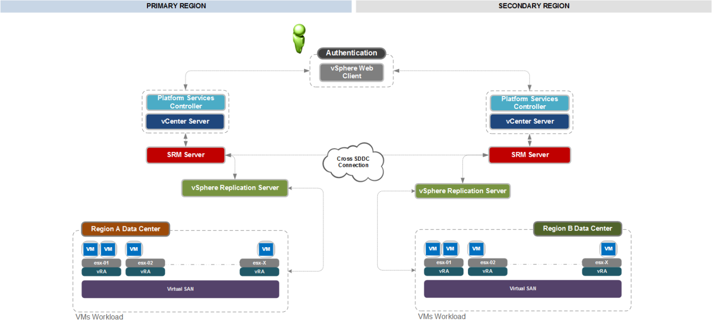
Dedicated network connectivity must exist between Region A and Region B, so that data from Region A can be replicated to Region B using VMware vSphere Replication, but also so that VMware Site Recovery Manager can coordinate the failover.
Region A has a management cluster of ESXi hosts with management application virtual machines that must be protected. Region B has a management cluster of ESXi hosts with sufficient free capacity to host the management applications from Region A. Each region has an instance of vCenter Server that manages the ESXi hosts within the region. Each region also has a Site Recovery Manager server and a Site Recovery Manager database. vSphere replication provides replication between the storage arrays and/or VSAN between Region A and Region B (See Figure 2).
The vCenter Server design includes a total of two virtual vCenter Server systems for the Management stacks. One Management Stack vCenter Server is located in Region A and one Management Stack vCenter Server is located in Region B. These are deployed within the same four-node ESXi management cluster within each region. Each vCenter Server provides specific functions as follows:
- VMware vCenter Server Management / Region A: Located within the Region A data center to provide management of the primary management cluster and integration with Site Recovery Manager.
- VMware vCenter Server Management / Region B: Located within the Region B data center to provide management of the recovery management cluster and integration with Site Recovery Manager.
Network Design
Physically moving a service from one region to another represents a networking challenge. Additional complexities can be introduced if applications have hard-coded IP addresses. Network addressing space and IP address assignment design considerations require that you choose to use either the same IP address or different IP address within the recovery region.
While protecting typical 3 tier web applications, this problem can be simplified by leveraging a load balancer to separate between a public reachable network segment, and a private network segment. On the public network segment, the web application is accessible via one or more virtual IP (VIP) addresses, while the inner working of the application are “hidden” on the isolated private network segment. Following this approach it is possible to treat the internal private network segment as a VLAN or VXLAN island without the requirement to change the IPv4 subnet between regions during a failover. Solely the external IPv4 address of the load balancer VIP changes between regions.
After a failover the recovered service is available under a different IPv4 address (VIP), which requires DNS entries to be changed. This can easily be accomplished in an automated manner (See Figure 3).
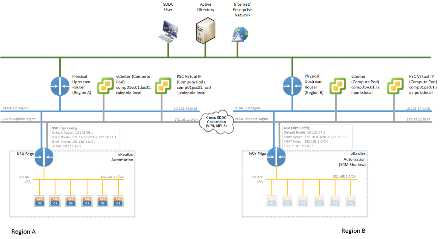
The vSphere Management networks (Figure 3, grey network) between SDDC regions have to be interconnected via VPN or MPLS. Various options exist for accomplishing such a cross-connect, ranging from VMware NSX Edge devices with IPSec VPN to various hardware based network products.
The IPv4 subnets within the VLAN “islands” (Figure 3, yellow network) are routed within the vSphere management network (Figure 3, grey network) of a region. Nodes within these “islands” are therefore reachable from within the SDDC (including Jump-Hosts, SSLVPN connections or alike). As these IPv4 subnets overlap across a region, care must be taken that these IPv4 subnet are not propagated beyond a region.
The public facing Ext-Management network (Figure 3, blue network) of both regions is assumed to be reachable by users of the SDDC and is also assumed to both connect to external resources, such as Active Directory or DNS.
The load balancers - here NSX Edge devices - across the two regions must be configured with the same settings (while taking into account the differing external IP addresses) for a given management application and it’s SRM shadow segment. This configuration sync needs to happen either manually or can be accomplished via scripting.
It is assumed that Active Directory and DNS services are running at both the primary and secondary location. It is advisable to use Anycast to make DNS Resolvers available under the same IPv4 address at different location, as well as using Global Traffic Management to make local Active Directory Domain Controllers available under a common global domain name.
Furthermore it is recommended to use the NSX DNS server functionality within a vPOD to provide DNS server capabilities to the nodes within the vPOD. This way each node leverages the NSX Edge of the vPOD as DNS resolver. This NSX Edge in return leverages a local DNS server as resolver.
Summary
Using the here described BC/DR strategy for the Software Defined Data Center (SDDC), not only simplifies the setup of the resource protection itself, but also simplifies the operation of the actual failover. Especially the concept of the previously introduced network container helps a lot in this scenario.
Leave a comment