
Building a Cumulus Networks VX cloud lab with Ravello Systems
Notice: This article is more than 8 years old. It might be outdated.
In a previous post I’ve already shown how to build a virtual network lab with Arista vEOS and VMware ESX. In this post we want to take this concept even further to the next level. Instead of Arista vEOS we will use the newly released Cumulus Networks Virtual Experience (VX) edition. And instead of VMware ESX we will use Ravello Systems, allowing us to use AWS or Google Compute Engine.
Elements used
Cumulus Networks provides a standard Linux based operating system for data center switches, thus simplifying dramatically the data center operations. If you are familiar with running and operating Linux on a regular server, managing a Cumulus Network based switch shouldn’t be a big challenge for you. Also you can now finally leverage the hundreds of existing management, automation and monitoring tools that you know and love for Linux. Cumulus Networks Virtual Experience (VX) is a community-supported virtual appliance that enables cloud admins and network engineers to preview and test Cumulus Networks technology at zero cost inside a virtual machine or standard X86 server.
Ravello Systems provides a Smart Labs solution on top of AWS and Google Compute Engine (GCE) based on nested virtualization. This allows you to run self-contained lab “capsules” with almost any kind of VMware or KVM based virtual machine in them. This approach - proven for years with the VMWorld labs - now allows you to use modern public clouds for test, training and demo purposes at a minimal cost. Specific for networking lab cases Ravello Systems provides virtual L2 networking on top of both AWS and GCE, allowing you to simulate very complex network scenarios.
Architecture
For this exercise we want to build a very simple two-leaf/two-spine virtual network architecture (See Figure 1).
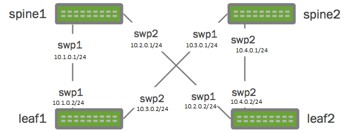
The architecture will include two spine switches (spine1 and spine2) as well as two leaf switches (leaf1 and leaf2), cross connected in a typical CLOS network architecture. For the four point-to-point connections between the devices we will use the depicted RFC1918 IP ranges, while making the management interface of the switches available over the internet (not depicted).
Getting Started
Before you can get started you need an account for Ravello Systems. You can conveniently sign-up for a free trial account. This account will allow you to use Ravello for free for 14 days. You do not need a credit card or any existing cloud credentials with AWS or GCE.
Next we need to download the Cumulus Networks VX images in QCOW2 format. This image will later be imported into Ravello Systems.
If you want to save time you can also use my pre-built Ravello Systems blueprint for Cumulus Networks VX. See further down for details.
Uploading the Cumulus Networks VX image into Ravello Systems
Once you have received your login credentials for your Ravello Systems account, you can start your cloud lab experience by uploading the Cumulus Networks VX images - in QCOW2 format - into Ravello Systems (See Figure 2).
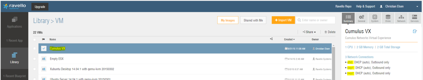
You can leave most of the settings as default, when importing the VM. Please note that you will need to add two network interfaces, resulting in a total of three network interfaces. It is recommended to call the first interface “eth0”, the second interface “swp1”, and the third interface “swp2”.
Creating an application
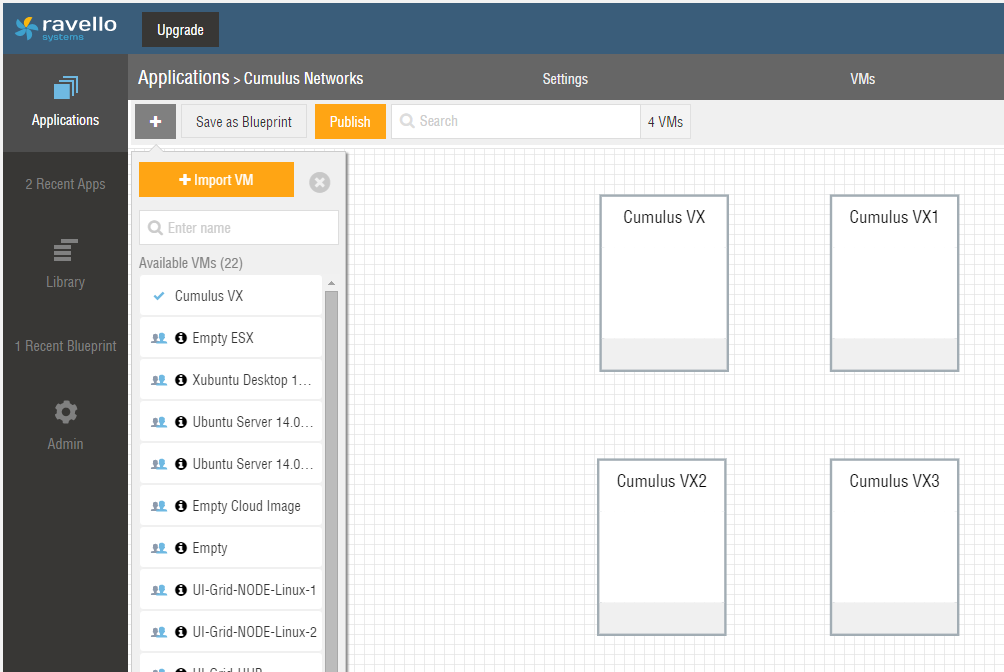
Next create an “application” within Ravello Systems that maps to your desired network architecture. Place four instance of the previously imported Cumulus Networks VX image into this application (See Figure 3). It is recommend to position them in a similar fashion to the network diagram in Figure 1. This will provide you a better overview and simplify the configuration.
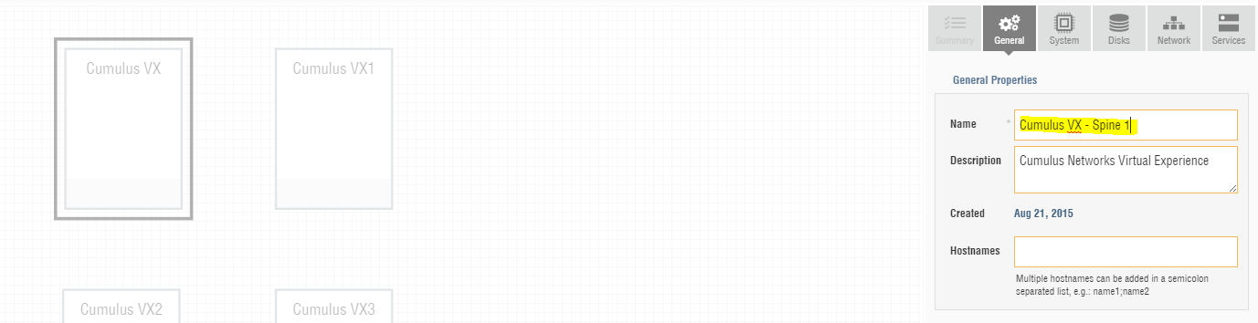
Next choose the first VM in your Ravello Systems application and give it a meaningful name (See Figure 4).
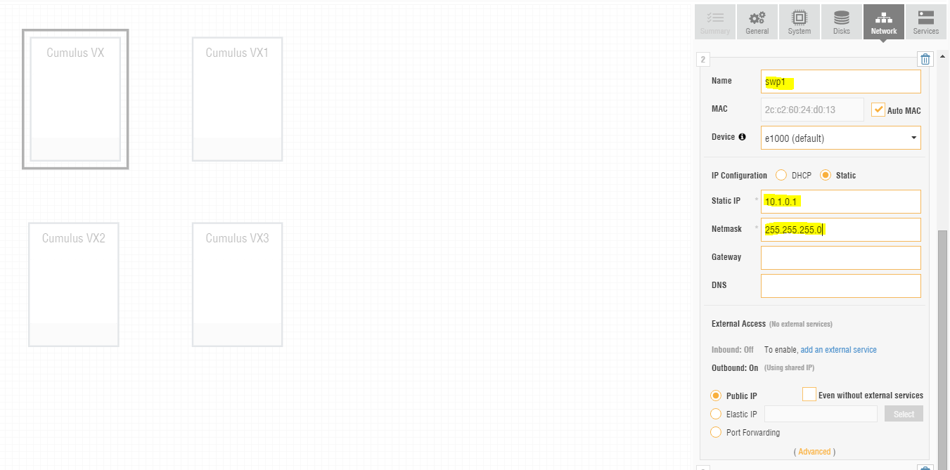
Also configure the interfaces “swp1” and “swp2” according to the network diagram in Figure 1. For this you have to change the IP configuration for each of the two interfaces from DHCP to static and enter the static IP address as well as network mask (See Figure 5).
Entering these IP information will not actually configure the interfaces correspondingly inside the Cumulus Networks VX device. Instead it will instruct Ravello Systems to place the interfaces on separate network segments (See Figure 6).
You should be able to see that by default all network interfaces would reside on the same network segment as it is the case for the so far unconfigured devices “Cumulus VX1”, “Cumulus VX2”, and “Cumulus VX3”.
For the configured device “Cumulus VX - Spine 1”, the interfaces “swp1” and “swp2” have already been moved to separate network segments.
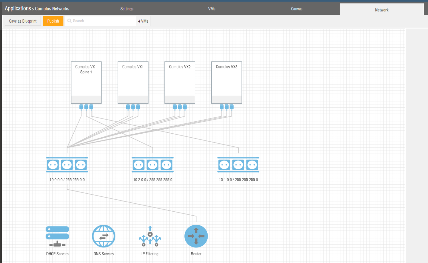
The default network segment 10.0.0.0/16 should remain connected to eth0 as it will provide us inbound and outbound Internet connectivity and therefor allow us to connect via SSH later.
Repeat the above steps on all Cumulus Network VX devices and provide each instance with a unique name and the network interface configuration corresponding to the network map in Figure 1.
The resulting network map within Ravello Systems should look like depicted in Figure 7.
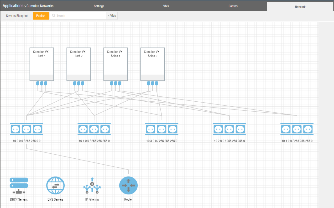
You should see the four point-to-point network segments with two connections per segment.
The fifth network segment, connecting to all devices provides external connectivity via the router symbol depicted at the bottom. This network segment connects to the management port “eth0” on the Cumulus Networks VX device.
Providing access via SSH
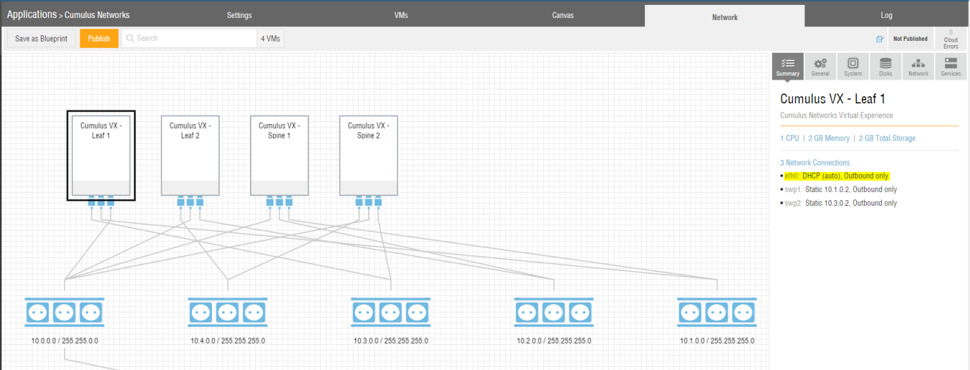
If you select a single Cumulus Networks VX instance within your Ravello Systems application, you can see that by default this VM only has outbound network connectivity via the eth0 interface (See Figure 8).
Once deployed you will be able to access each of the Cumulus Networks VX devices via the build-in Ravello Systems console. While the Ravello Systems console is a great way to interact with virtual machines, we also want to be able to use SSH access for accessing each of the Cumulus Networks VX devices. This will simplify the configuration in subsequent steps and feel more natural.
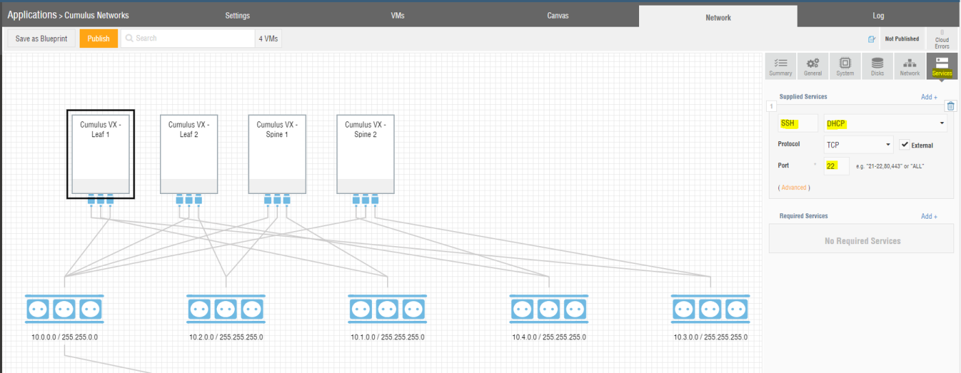
For doing so, you have to add a “Service” for each of the VMs within your Ravello Systems application and configure it for SSH with port TCP/22 against the interface DHCP. The interface DHCP corresponds to eth0 (See Figure 9).
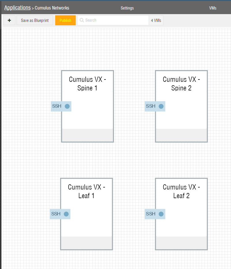
Returning to the Canvas view within Ravello Systems, you will see the four Cumulus Networks VMs with the SSH service configured (See Figure 10).
Deploy the network testbed
Next we want to deploy - called “Publish” in Ravello Systems terms - the network testbed to either AWS or GCE, so that we can use it. To do so, just hit “Publish” and confirm the default settings to publish the testbed in the most cost effective location (See Figure 11).
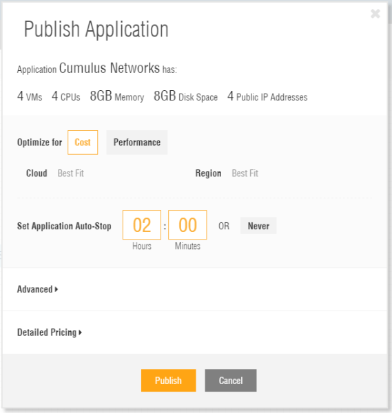
By default the tesbed will only be deployed for 2 hours. After this it will be shut down automatically. If you need your testbed longer, adapt the time accordingly.
Accessing the network testbed
After a few minutes your testbed should be published to either AWS or GCE and each VM should be up and running. At this point you can connect via SSH to each of the Cumulus Networks VX nodes.
Use the hostname or IP address shown for each VM within the Ravello Systems Console along with the username “cumulus” and the password “CumulusLinux!” (See Figure 12).
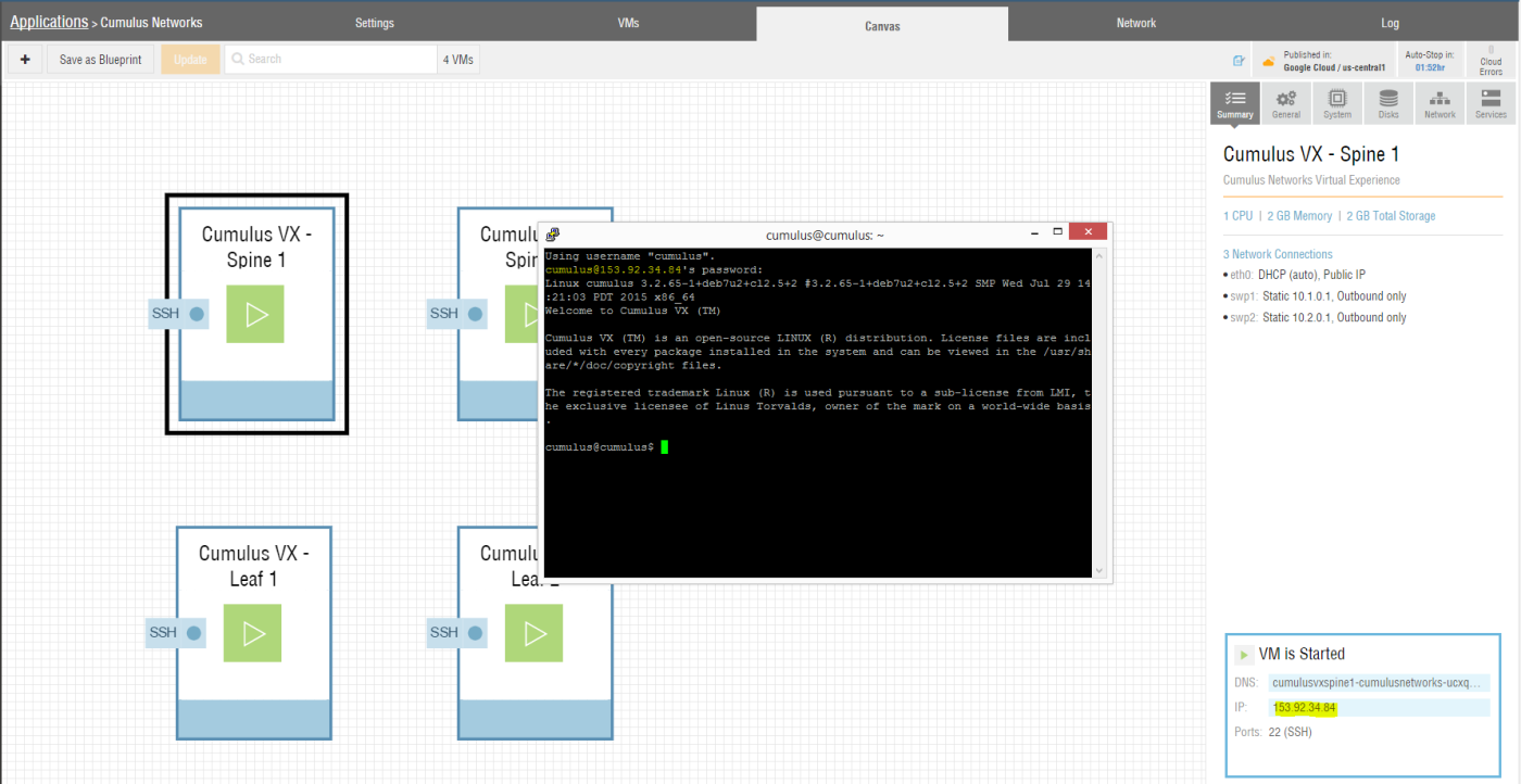
Keep in mind, that the Cumulus Network VX nodes are still unconfigured at this point. The IPv4 address configuration for the VMs in Ravello Systems was only for generating the different networks segments within Ravello Systems and does not apply to the network configuration within the Cumulus Networks VX node.
Basic network testbed configuration
In this step we want to perform basic network configuration and at least enable the Cumulus Networks VX nodes to communicate with each other. For this we will configure all “swp” interfaces on all devices as a routed port with the IPv4 address depicted in Figure 1.
We will start by connecting to Spine1 via SSH. Next configure the IPv4 addresses via editing the file “/etc/network/interfaces”. You can do so using “sudo” and your favorite browser:
cumulus@cumulus$ sudo vi /etc/network/interfaces
Add the following lines to the end of the file:
auto swp1
iface swp1
        address 10.1.0.1

auto swp2
iface swp2
        address 10.2.0.1
Next restart the Cumulus Networks VX networking for the configuration to be applied:
cumulus@cumulus$ sudo service networking restart
Repeat the above steps for the other three devices. Remember to adapt the IPv4 addresses in the file “/etc/network/interfaces” for the interfaces “swp1” and “swp2” according to the network diagram in Figure 1.
Testing your network setup
Test the functionality of your basic network lab. First look at the available interfaces and their IP addresses via standard Linux commands:
cumulus@spine1$ ifconfig
eth0      Link encap:Ethernet  HWaddr 2c:c2:60:46:1e:68
          inet addr:10.0.0.5  Bcast:10.0.255.255  Mask:255.255.0.0
          inet6 addr: fe80::2ec2:60ff:fe46:1e68/64 Scope:Link
          UP BROADCAST RUNNING MULTICAST  MTU:1500  Metric:1
          RX packets:181 errors:0 dropped:0 overruns:0 frame:0
          TX packets:120 errors:0 dropped:0 overruns:0 carrier:0
          collisions:0 txqueuelen:1000
          RX bytes:22332 (21.8 KiB)  TX bytes:15935 (15.5 KiB)

lo        Link encap:Local Loopback
          inet addr:127.0.0.1  Mask:255.0.0.0
          inet6 addr: ::1/128 Scope:Host
          UP LOOPBACK RUNNING  MTU:16436  Metric:1
          RX packets:1 errors:0 dropped:0 overruns:0 frame:0
          TX packets:1 errors:0 dropped:0 overruns:0 carrier:0
          collisions:0 txqueuelen:0
          RX bytes:28 (28.0 B)  TX bytes:28 (28.0 B)

swp1      Link encap:Ethernet  HWaddr 2c:c2:60:46:43:f7
          inet addr:10.1.0.1  Bcast:0.0.0.0  Mask:255.255.255.0
          inet6 addr: fe80::2ec2:60ff:fe46:43f7/64 Scope:Link
          UP BROADCAST RUNNING MULTICAST  MTU:1500  Metric:1
          RX packets:7 errors:0 dropped:0 overruns:0 frame:0
          TX packets:6 errors:0 dropped:0 overruns:0 carrier:0
          collisions:0 txqueuelen:1000
          RX bytes:541 (541.0 B)  TX bytes:652 (652.0 B)

swp2      Link encap:Ethernet  HWaddr 2c:c2:60:32:7b:88
          inet addr:10.2.0.1  Bcast:0.0.0.0  Mask:255.255.255.0
          inet6 addr: fe80::2ec2:60ff:fe32:7b88/64 Scope:Link
          UP BROADCAST RUNNING MULTICAST  MTU:1500  Metric:1
          RX packets:8 errors:0 dropped:0 overruns:0 frame:0
          TX packets:6 errors:0 dropped:0 overruns:0 carrier:0
          collisions:0 txqueuelen:1000
          RX bytes:662 (662.0 B)  TX bytes:652 (652.0 B)

cumulus@spine1$
For each device within your testbed you should see the following four interfaces:
- eth0: IPv4 address on the 10.0.0.0/16 network, providing you inbound and outbound network connectivity
- lo: Loopback interface with IPv4 address 127.0.0.1/8 and IPv6 address ::1/128
- swp1: Switchport interface with IPv4 address, connected to another spine or leaf switch
- swp2: Switchport interface with IPv4 address, connected to another spine or leaf switch
Next verify if you can ping the adjacent interface of another connected switch. From the device “Spine1” we can try to ping the interface “swp1” with the IPv4 address 10.1.0.2 on the switch “Leaf1”:
cumulus@spine1$ ping -c 3 10.1.0.2
PING 10.1.0.2 (10.1.0.2) 56(84) bytes of data.
64 bytes from 10.1.0.2: icmp_req=1 ttl=64 time=2.67 ms
64 bytes from 10.1.0.2: icmp_req=2 ttl=64 time=0.892 ms
64 bytes from 10.1.0.2: icmp_req=3 ttl=64 time=0.769 ms

--- 10.1.0.2 ping statistics ---
3 packets transmitted, 3 received, 0% packet loss, time 2003ms
rtt min/avg/max/mdev = 0.769/1.445/2.676/0.872 ms
cumulus@spine1$
The pings should succeed.
Save time, use a Ravello Systems Blueprint
Instead of going through the above steps you can also use my pre-built Ravello Systems blueprint for Cumulus Networks VX. Just add this public accessible blueprint to your own Ravello Systems library and deploy the above described network lab in a few minutes.
More capabilities
Cumulus Networks VX provides a lot more capabilities than what I was able to showcase in this blog post. With the above described simple testbed you are now empowered to explore these capabilities.
Have a look at the Cumulus Network Technical Documentation to get inspired on what you can do.
Leave a comment