
OpenStack with vSphere and NSX - Part 1: Install and configure the VMware NSX appliances
Notice: This article is more than 10 years old. It might be outdated.
Welcome to part 1 of the series on installing OpenStack with VMware vSphere and VMware NSX. This series shows the deployment of an OpenStack cloud that leverages VMware vSphere – along with it’s well-known enterprise-class benefits such as VMotion – as the underlying Hypervisor. In addition, network virtualization within OpenStack will be provided via NSX as a Neutron plugin. This allows the creation of virtual networks within OpenStack that consist of L2 segments and can be interconnected via L3 to each other or the outside world.
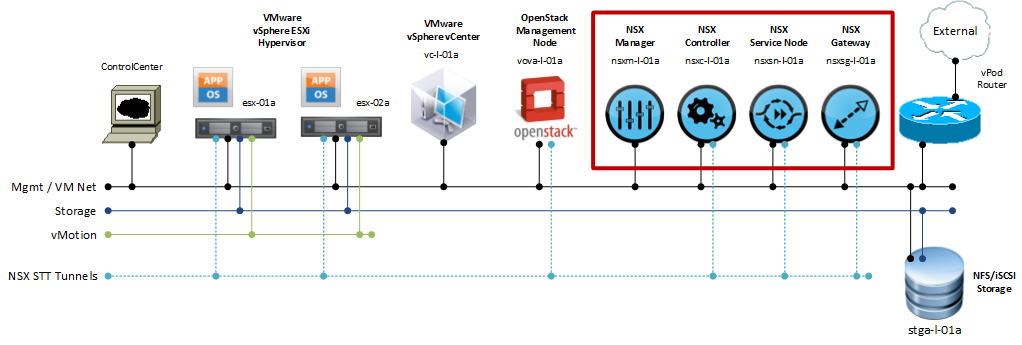
VMware NSX components and their role
A VMware NSX setup consists of various components. Each of them has a specific role in the overall setup. Some components are deployed in form of an appliance, other are installed as a module into the Hypervisor:
-
NSX Controller
The NSX Controllers implements a network control plane for controlling the Open vSwitch (OVS) devices that perform packet forwarding. Controller Cluster nodes cooperate to manage all OVS devices and enforce consistency between the logical network view (defined via the NSX API) and the transport network view (implemented by OVS-enabled access switches). -
Transport Nodes
Hypervisors, NSX Service Nodes, and NSX Gateways are represented in NSX as transport nodes. A transport node is any physical or virtual device that runs Open vSwitch and is managed by the NSX Controller to implement logical networks. How the NSX Controller manages the transport node depends on the role of that transport node:-
Hypervisors
Leverage an Open vSwitch to provide network connectivity for VM-based workloads. Like Service Nodes and Gateways, hypervisors are represented in NSX using the transport node entity. -
Gateways
An NSX Gateway connects logical networks to the data center’s physical network or to physical applications. -
Service Node
NSX Service Nodes offload network packet processing from hypervisor Open vSwitches, such as broadcast, unknown unicast and multicast (BUM) replication and CPU-intensive cryptographic processing
-
Hypervisors
-
NSX Manager
The NSX Manager provides a GUI for operators to setup and configure an NSX network. It is not used by OpenStack itself and could be removed in the case that the operator uses CLI commands for all setup and configuration steps.
If you want to learn more about the architecture of VMware NSX, check out the VMware NSX Network Virtualization Design Guide (PDF).
Install Virtual Appliances
As a first step we will install the NSX appliances as form of a virtual appliance, thus inside a VM (See figure 1). VMware provides the software for the NSX appliances as an ISO file.
Inside VMware vSphere create four virtual machines with the following settings:
- Guest Operating System: Ubuntu Linux (64-bit)
- CPU: 1
- Memory: 2 GB
- Network: 1 vNIC (E1000)
- Disk Size: 16 GB
Note that these values are well below the supported minimum requirements for VMware NSX in a production environment. As this setup is for test, proof-of-concept and education purposes only, it is sufficient to deploy it with the above settings.
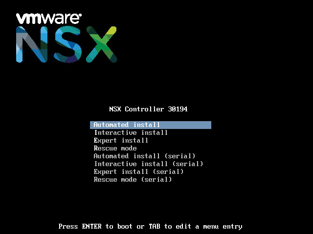
Next mount the corresponding ISO image to each of the four appliances. The VMs should boot via CD-ROM and display an installation screen (See Figure 2). Choose Automated Install to proceed.
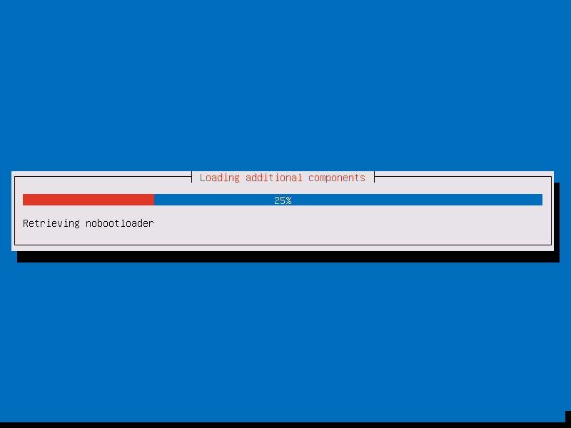
An automated installation of the NSX appliance will start. This can take several minutes. (See Figure 3)
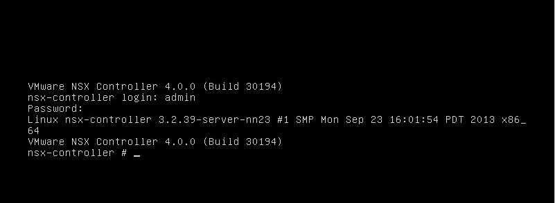
At the end of the installation you will be greeted with a login screen. Login with the username admin and the password admin. (See Figure 4)
Basic Configuration
After you are logged in, we will perform the basic configuration. This basic configuration will be the same for all four appliances. I therefore recommend, that you first complete the installation of all four appliances.
First, configure a new admin password for each of the appliances with the command set user <username> password:
nsx-controller # set user admin password
Enter new password:
Retype new password:
Password updated successfully.
nsx-controller #
Next, configure the appliance’s hostname with the set hostname <hostname> command:
nsx-controller # set hostname nsxc-l-01a
nsxc-l-01a #
Although NSX appliances are based on Ubuntu Linux they do not use eth0 as the network interface. Instead they use a so-called integration bridge interface for network connectivity. This device is called breth0. In this step we will configure an IP address on this physical interface via the command set network interface breth0 ip config static <IP address> <Netmask>. Notice that the NSX appliance will clear the DNS settings if it had acquired an IP address and DNS settings via DHCP before.
nsxc-l-01a # set network interface breth0 ip config static 192.168.110.101 255.255.255.0
Setting IP for interface breth0...
Clearing DNS configuration...
nsxc-l-01a #
You can verify the network settings with the command show network interface breth0:
nsxc-l-01a # show network interface breth0
IP config: static
Address: 192.168.110.101
Netmask: 255.255.255.0
Broadcast: 192.168.110.255
MTU: 1500
MAC: 00:50:56:12:34:56
Admin-Status: UP
Link-Status: UP
SNMP: disabled
nsxc-l-01a #
Next, it’s time to add a default route via the command add network route 0.0.0.0 0.0.0.0 <gateway>:
nsxc-l-01a # add network route 0.0.0.0 0.0.0.0 192.168.110.1
nsxc-l-01a #
Again, we can verify the settings via the command show network route:
nsxc-l-01a # show network route
Prefix/Mask          Gateway          Metric  MTU     Iface
0.0.0.0/0            192.168.110.2    0       intf    breth0
192.168.110.0/24     0.0.0.0          0       intf    breth0
nsxc-l-01a #
Now add the DNS servers via the command add network dns-server <Server name>:
nsxc-l-01a # add network dns-server 192.168.110.10
nsxc-l-01a #
Last, but not least add the NTP server via the command add network ntp-server <Server name>:
nsxc-l-01a # add network ntp-server 192.168.110.1
* Stopping NTP server ntpd                                               [ OK ]
Synchronizing with NTP servers. This may take a few seconds ...
12 Dec 20:34:51 ntpdate[3241]: step time server 192.168.110.1 offset - 7.140147
sec
* Starting NTP server ntpd
nsxc-l-01a #
All the above basic configuration steps are the same for all four NSX appliances, except that each appliance needs to receive its own IP address and hostname. Therefore ensure that you complete the above steps before moving on.
Node-specific configuration
Next we will perform the node specific configuration on the Controller node, the Gateway node and the Service node. The configuration of the Management VM is already complete with the steps above.
Controller Node
We need to specify for the controller node which IP address should be used as the management address as well as the API address. This is necessary for the case that an NSX controller is deployed with multiple IP addresses in different subnets. As mentioned earlier I’ll keep it single, utilizing only a single subnet.
First, set the IP address the controller should use for management traffic with the command set control-cluster management-address <IP address>
nsxc-l-01a # set control-cluster management-address 192.168.110.101
nsxc-l-01a #
Next tell the NSX controller which IP address to use for the switch manager traffic (this is the traffic that communicates with OVS interfaces) via the command set control-cluster role switch_manager listen-ip <IP address>
nsxc-l-01a # set control-cluster role switch_manager listen-ip 192.168.110.101
nsxc-l-01a #
Then instruct the controller which IP address to use for the API interface traffic (this is the interface that handles northbound REST API traffic) with the command set control-cluster role api_provider listen-ip <IP address>
nsxc-l-01a # set control-cluster role api_provider listen-ip 192.168.110.101
nsxc-l-01a #
Once you have completed these steps, you can turn up the controller cluster with the command join control-cluster <own IP address>. Notice that for the first controller you are basically joining the controller to itself. In the case that the controller has multiple IP addresses, the address to use is the one you specified when you set the management IP address earlier.
nsxc-l01a # join control-cluster 192.168.110.101
Clearing controller state and restarting
Stopping nicira-nvp-controller: [Done]
Clearing nicira-nvp-controller's state: OK
Starting nicira-nvp-controller: CLI revert file already exists
mapping eth0 -> bridge-pif
ssh stop/waiting
ssh start/running, process 3908
mapping breth0 -> eth0
mapping breth0 -> eth0
ssh stop/waiting
ssh start/running, process 4057
Setting core limit to unlimited
Setting file descriptor limit to 100000
 nicira-nvp-controller [OK]
** Watching control-cluster history; ctrl-c to exit **
===================================
Host nsxc-l-01a
Node a57282ce-87fe-44ed-9db1-9dcc21204e33 (192.168.110.101)
  ---------------------------------
  12/12 20:53:20: Joining cluster via node 192.168.110.101
  12/12 20:53:20: Waiting to join cluster
  12/12 20:53:20: Joined cluster; initializing local components
  12/12 20:53:24: Initializing data contact with cluster
  12/12 20:53:32: Fetching initial configuration data
  12/12 20:53:34: Join complete
nsxc-l-01a #
Note that for the second and third controllers in a cluster, you would point them to the IP address of any existing controller in the cluster. But as we are only using a single controller here, this is not necessary.
Gateway Node and Service Node
The Gateway nodes as well as the service nodes need to be made aware of the controller cluster.
On both nodes this is done with the command add switch manager <IP address of a controller node>:
nsxg-l-01a # add switch manager 192.168.110.152
Waiting for the manager CA certificate to synchronize...
Manager CA certificate synchronized
nsxg-l-01a #
This completes the installation of the NSX appliances. Next in the series on OpenStack with vSphere and NSX is Part 2 with the creation and configuration the VMware NSX cluster via the NSX manager. While we finished the installation and basic configuration of the VMware NSX appliances in this post, the next post will show how to use the NSX Manager’s web-based GUI to join these parts together and build the basic functionality of an NSX installation.
Leave a comment